
CMSG120N013MDG Data Report: Key Parameters and Cost-Performance Analysis of Si/SiC Hybrid Module
Deep Analysis of the "Efficiency Balance Master" in Power Electronics
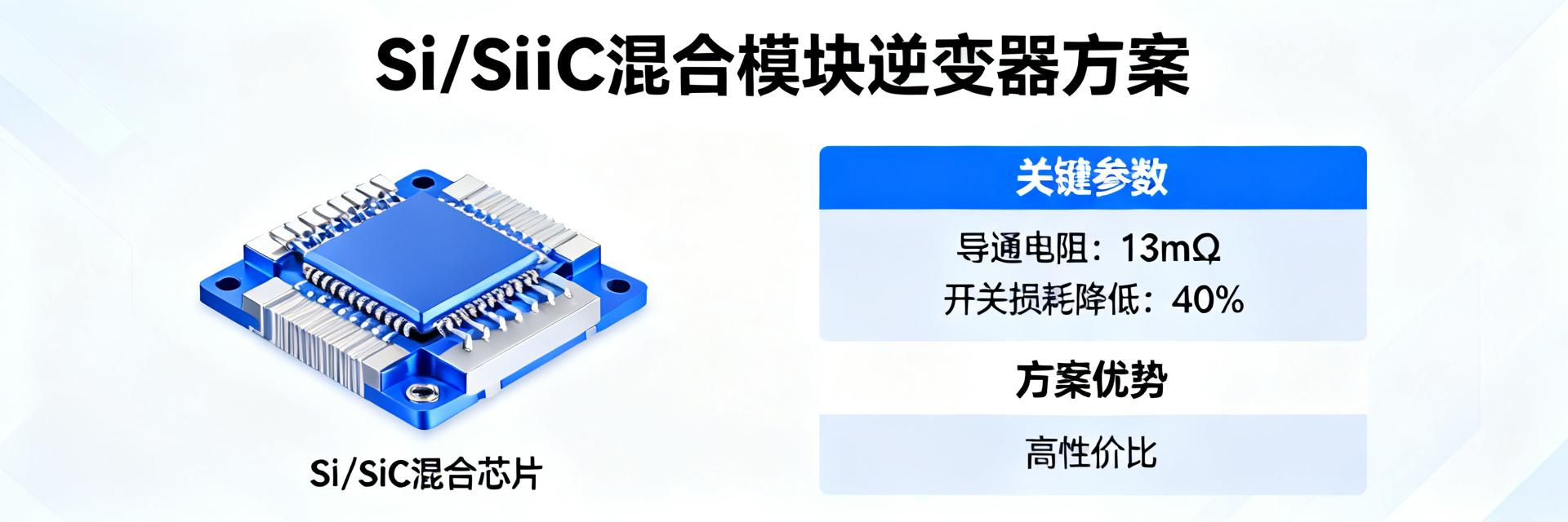
In the field of power electronics, where the balance between high efficiency and low cost is pursued, Si/SiC hybrid modules are becoming the "sweet spot" for next-generation inverter designs. Taking the 1200V/120A specification CMSG120N013MDG as an example, its typical on-resistance is as low as 13 mΩ, and switching losses are reduced by more than 40% compared to traditional pure Si IGBT solutions. How does this device achieve a balance between performance and cost? This article will deeply analyze its key parameters and true cost-performance ratio based on the official datasheet.
Current PV inverters and energy storage systems (ESS) face increasingly stringent requirements for power density, and designers are under dual pressure from efficiency and budget. As a hybrid solution launched by onsemi, CMSG120N013MDG aims to solve this industry pain point. It is not just a component, but a bridge to next-generation high-efficiency power systems.
I. Si/SiC Hybrid Modules: Why They Are the High Cost-Performance Choice?
To understand the value of CMSG120N013MDG, one first needs insight into the limitations of pure Si technology and full SiC solutions. In high-frequency applications above 20kHz, pure Si IGBTs suffer from tail current and switching losses that significantly reduce system efficiency. While full SiC MOSFETs offer excellent switching performance, their high wafer costs and complex gate driver circuits often stretch project budgets to their limits.
Pure Si IGBT
High-frequency losses are large, and tail current exists. Low cost, but limits system power density.
Full SiC MOSFET
Ultra-low loss, ultra-high frequency. Peak performance, but wafer cost is extremely high.
Hybrid Module (CMSG120N013MDG)
Performance aligned with SiC, cost aligned with IGBT. System efficiency is close to full SiC, with costs reduced by over 30%.
1.1 The Technical "Gap" Between Pure Si and Full SiC
Pure Si IGBTs exhibit significant tail current during turn-off, which causes turn-off loss (Eoff) to increase sharply with temperature, limiting high-frequency application possibilities. Full SiC MOSFETs adopt a unipolar device structure with no tail current and fast switching speeds, but their high chip cost remains a major barrier to large-scale deployment. CMSG120N013MDG was born precisely to bridge this "gap".
1.2 Positioning and Architecture of CMSG120N013MDG
CMSG120N013MDG is not a simple assembly of IGBT and SiC diodes, but a finely designed integrated module. Its internal topology cleverly combines the excellent conduction characteristics of Si IGBTs with the low switching loss advantages of SiC MOSFETs. Through precise chip proportioning, it maintains a low collector-emitter saturation voltage (VCE(sat)) while utilizing the high-speed switching capability of the SiC portion to significantly suppress voltage spikes and energy losses during turn-off.
II. Deep Analysis of CMSG120N013MDG Key Parameters
Parameters in the datasheet are the cornerstone of design. We will focus on three core parameters that directly affect system efficiency, thermal management, and reliability, interpreting the engineering significance behind the numbers.
| Parameter | Typical Value (Tc=25°C) | Typical Value (Tc=125°C) | Impact on System |
|---|---|---|---|
| VCE(sat) (IGBT Part) | 1.6 V | 1.9 V | Determines conduction loss, affects full-load efficiency |
| RDS(on) (SiC Part) | 13 mΩ | 18 mΩ | Affects light-load efficiency and switching characteristics |
| Eon + Eoff (Switching Loss) | 7.0 mJ | 8.5 mJ | Determines thermal loss at high frequency and heatsink size |
2.1 Conduction Characteristics: Synergistic Effect of VCE(sat) and RDS(on)
Under high current operating conditions, the IGBT's saturation voltage VCE(sat) is the dominant loss. In CMSG120N013MDG, the typical VCE(sat) remains stable at around 1.9V even at 125°C junction temperature, ensuring efficiency during high power transmission. At light loads or specific current ranges, the low RDS(on) of the parallel SiC MOSFET reduces conduction loss. This synergy optimizes total conduction loss across the entire load range.
2.2 Switching Characteristics: Eon/Eoff Loss and Reverse Recovery
Switching loss is the "heat source" of high-frequency design. Compared with pure Si IGBT modules of the same current rating, the total switching loss (Eon+Eoff) of CMSG120N013MDG can be reduced by 40%-50%. This is mainly due to the zero reverse recovery characteristics of SiC diodes or MOSFETs, which almost eliminates tail current during IGBT turn-off and reverse recovery spikes of silicon diodes. This advantage is particularly prominent at switching frequencies exceeding 20kHz.
III. Cost-Performance Model: From BOM Cost to Total Cost of Ownership
Evaluating chip value cannot only look at the unit price. We introduce the Total Cost of Ownership (TCO) model to quantify the true cost-performance ratio of CMSG120N013MDG from four dimensions.
3.1 BOM Cost vs. Heat Dissipation Cost
Although the unit cost of CMSG120N013MDG is higher than that of a pure silicon IGBT module of the same specification, the system-level cost savings it brings are significant. Due to higher efficiency and lower losses, the required heatsink volume and weight can be reduced by 20%-30%, and the associated fan cost and chassis space are also reduced. At the overall BOM level, adopting hybrid modules often achieves a total cost equal to or even better than pure Si solutions.
3.2 Long-Cycle Operating Electricity and Reliability Return
Assuming a 100kW inverter runs for 4000 hours a year, with electricity costs calculated at 0.6 RMB/kWh. Compared with conventional IGBT solutions, the use of CMSG120N013MDG can save tens of thousands of RMB in electricity bills annually due to a 2%-3% efficiency increase. These saved operating costs are enough to cover the initial price difference of the module within 2-3 years.
"Choosing CMSG120N013MDG is not a simple technical upgrade, but a financial decision with a clear payback period. It allows users to exchange a controllable initial investment for quantifiable long-term operating gains."
IV. Application Practice and Design Key Points of CMSG120N013MDG
4.1 Typical Application Scenarios: PV Inverters and ESS
In PV inverters, CMSG120N013MDG can effectively improve MPPT efficiency and DC-AC conversion efficiency. Due to faster switching speeds, lower harmonic distortion and higher power density can be achieved. In energy storage systems, its bidirectional operation characteristics (rectification and inversion) both benefit from low switching losses.
4.2 Driver and Thermal Design Key Considerations
Driving a hybrid module is not as simple as paralleling the drive signals of IGBT and SiC MOSFET. To avoid the risk of parasitic turn-on, drive timing must be precisely controlled, and independent gate resistors are recommended. In terms of thermal design, it is recommended to limit the maximum junction temperature (Tj) to below 150°C to balance performance with long-life reliability.
V. Selection Action Guide: When to Choose Hybrid Modules?
5.1 Three Characteristics of the "Hybrid Module Optimal Solution"
- Operating frequency exceeds 16kHz: Switching loss becomes the main contradiction.
- Strict volume restrictions: Need to reduce heatsink volume by reducing losses.
- Balance of initial cost and efficiency: Expect to recover investment within 2-4 years.
5.2 Final Choice Between Pure Si/Full SiC Solutions
If project costs are extremely sensitive and the frequency is below 10kHz, pure Si IGBT remains the economic choice. If pursuing ultimate efficiency and the budget is sufficient, full SiC MOSFET solutions are the first choice. Between the two, CMSG120N013MDG is that highly competitive "golden solution".
Key Summary
- Precise Positioning of CMSG120N013MDG: Achieves an ideal balance between cost and performance by integrating Si IGBT and SiC MOSFET.
- Key Parameter Advantages: Switching loss is reduced by more than 40% compared to traditional Si solutions, making thermal management easier.
- TCO Value Highlights: Investment payback can be achieved within 2-3 years by reducing cooling costs and saving operating electricity.
Frequently Asked Questions
Q: Compared with full SiC MOSFET modules, what are the main disadvantages of CMSG120N013MDG?
The main disadvantage lies in ultimate efficiency. For very high frequency (such as >100kHz) occasions, full SiC still has advantages. However, considering cost, CMSG120N013MDG provides an excellent alternative in the 20kHz-40kHz frequency range.
Q: When designing with CMSG120N013MDG, does the drive circuit need special design?
Yes. It is recommended to use negative voltage turn-off and configure independent gate resistors for the IGBT and SiC parts separately, while strictly controlling layout and wiring to reduce parasitic inductance.
Q: How is the long-term reliability of this hybrid module?
Due to its low-loss characteristics, the overall junction temperature of the module is usually lower than that of pure Si solutions, which helps improve power cycling capability. With correct thermal design, its reliability is very trustworthy.

